
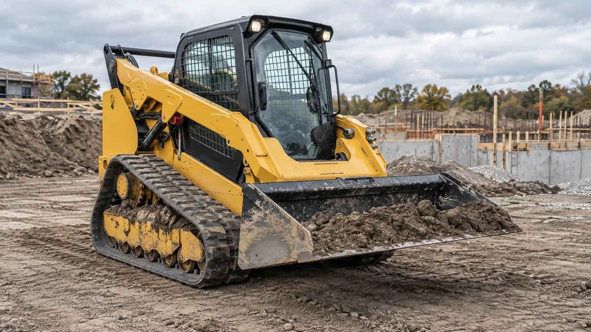
How to choose a skid-steer cold planer attachment
Choose a cold planer by matching the exact carrier and attachment first, then selecting a drum width and cutting arrangement that suit the repair. Working width, hydraulic flow, pressure, attachment weight and approved controls all matter. Maximum cutting depth is a machine specification, not a promise of productive one-pass removal at that depth.
A cold planer attachment mills asphalt or concrete with a rotating cutting drum. It fills a different role from a bucket, breaker or walk-behind saw: the buying question is whether an approved carrier-and-planer combination can produce the required surface and repair geometry efficiently.
A real specification example: Cat PC306
Caterpillar's PC306 product page, checked October 28, 2026, provides a useful example of the information a quote should contain:
| PC306 reference item | Manufacturer-listed value |
|---|---|
| Working width | 23.6 in / 600 mm |
| Maximum cutting depth | 6.7 in / 170 mm |
| Hydraulic requirement | High flow |
| Optimal hydraulic flow | 26–33 US gpm / 98–125 L/min |
| Optimal hydraulic pressure | 3,300–4,000 psi / 230–280 bar |
| Attachment weight | 2,107.6 lb / 956 kg |
This is an example of one product's published requirements, not a universal planer specification or an approval to use it on another brand. Verify the exact product generation and installed drum. A PC306, a PC306B and a different-width planer should not be treated as identical listings.
Why high flow alone does not establish compatibility
A loader advertised at 30 gpm appears to fall within the example's flow range, but that observation clears only one comparison item. Working pressure, approved carrier match, attachment weight, mechanical interface, return plumbing, controls, cooling and any required protection still need confirmation.
Conversely, a carrier with a larger maximum flow may require an approved reduced-flow setting to stay within a particular planer's allowed range. Do not use the high-flow badge as permission to connect and operate an attachment. Ask the manufacturer or authorized dealer to confirm the complete combination.
Use the standard-flow vs high-flow guide and matching worksheet to document the requirements before arranging a demonstration.
Drum width and pass count: a planning example
Suppose a repair strip is 48 inches wide and the planned overlap between adjacent passes is 2 inches. For equal-width adjacent passes, covered width is first-pass width + additional passes × (drum width − overlap). The following is a geometry example using hypothetical nominal drum widths:
| Nominal drum width | Coverage with two passes | Passes needed for at least 48 in |
|---|---|---|
| 18 in | 18 + 16 = 34 in | 3 passes cover 50 in |
| 24 in | 24 + 22 = 46 in | 3 passes cover 68 in |
The example shows why “twice the drum width” is not the same as useful two-pass coverage when overlap is required. These nominal widths are not the PC306's exact 23.6-inch value. Use the actual installed drum width, the specified repair geometry and an appropriate overlap in your own plan.
Pass count alone is not production. Cutting depth, material hardness, bit condition, travel speed, maneuvering and cleanup can change total time. A wider tool should be evaluated on the carrier it will actually use, under comparable conditions, rather than assumed to finish every job faster.
Turn a demonstration into a useful production record
Write down the surface type, intended removal depth, drum width, measured completed area, productive minutes, turning and cleanup time, and the approved carrier settings. Record bit condition before and after the demonstration. Use that record to compare a rental quote or subcontracted milling price with ownership.
Do not price a full job from a brief run in softer material at a shallower cut. Keep mobilization, traffic arrangements, debris handling, disposal, operator labor and surface inspection separate from the tool's productive cutting time.
A quotation checklist for planer work
- Exact carrier model, serial range and installed hydraulic package.
- Planer model, drum width, tooth arrangement and intended material.
- Manufacturer-approved combination, required controls and connections.
- Required working depth and finished repair width.
- Wear-part availability, replacement cost and inspection procedure.
- Dust-control and operator-protection provisions required for the application.
- Transport and handling arrangements for the attachment's actual weight.
Keep personnel outside the operating exclusion area, follow the manufacturer's operating instructions and use the required dust controls. This buying guide does not provide a cutting procedure or permission to mill an unknown pavement, buried service or structural surface.
Which comparison should you read next?
If you are choosing the carrier as well as the tool, compare the 299D3 and 333 P-Tier hydraulic packages. For loader-capacity terminology, see ROC at 35% vs 50%. Keep attachment operating requirements separate from the carrier's engine horsepower and bucket ratings.
Primary references and calculation basis
- Caterpillar PC306 specifications: reference dimensions, hydraulic requirements and weight.
- Bobcat concrete and asphalt attachment guidance: carrier-flow matching and production considerations.
The pass-count table is an original geometric planning example, not an OEM production claim. Site conditions and the approved operating instructions determine the real work plan.


